Multi-Speed RC Vehicle Design
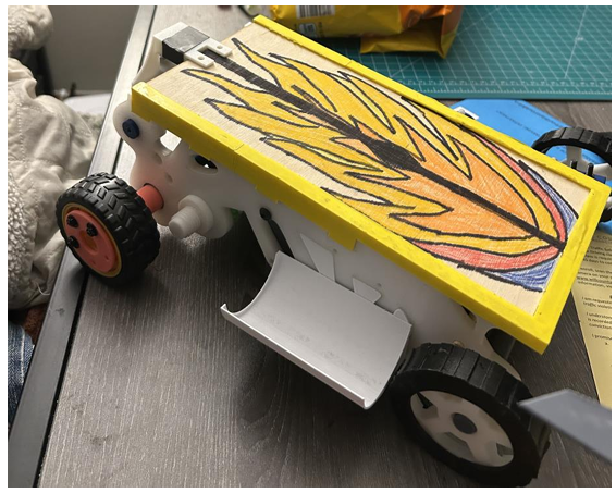
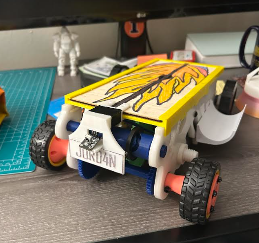
Designed and prototyped a custom remote-controlled vehicle centered around a servo-actuated, multi-speed transmission.
Project Overview
The project followed the complete engineering design process from customer requirements and concept selection through CAD, mechanical analysis, manufacturing, testing, and iterative redesign. The final iteration of the design was then be tested to see if it was capable of succeeding at the following challenges:
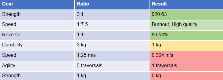
Achieve a speed of 1.25 m/s over an 8-meter distance
Consecutively travel backwards and forwards by 1-meter 8 times over the span of 60 seconds
Drive up a 2-meter, 15° incline while carrying a 1-kg weight in
Withstand the impact of a 3-kg load dropped from a distance of 0.25 meters above the ground
Achieve a minimum transmission efficiency of 40%
My Contributions
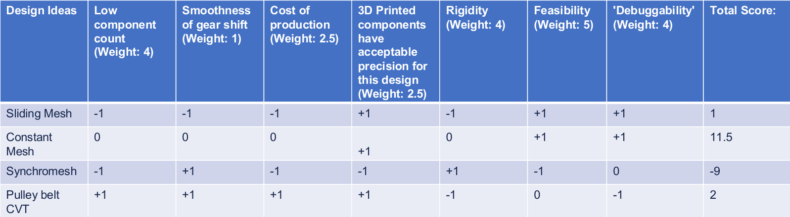
● Design Selection: Created weighted Pugh matrices to evaluate transmission and shifting concepts based on feasibility, manufacturability, rigidity, cost, shifting performance, and other design criteria.
● Gear Design: Developed the gear ratios and gear geometry used to provide separate speed, strength, and reverse configurations.
● Mechanical Analysis: Led the preliminary engineering calculations and design assumptions, including vehicle dynamics, required acceleration, wheel torque, motor power, drivetrain efficiency, and preliminary performance predictions.
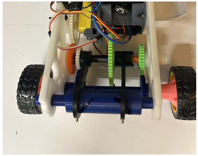
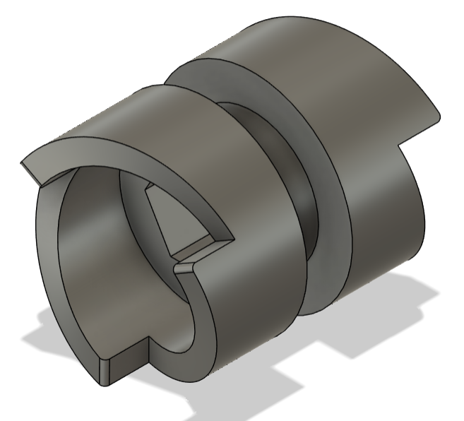
● Transmission Design: Designed the transmission's dog clutches, selector forks, and servo-driven barrel cam, converting servo rotation into controlled gear engagement.
● Embedded Controls: Programmed the IR remote-control system, mapping remote inputs to motor, transmission, and vehicle control commands.
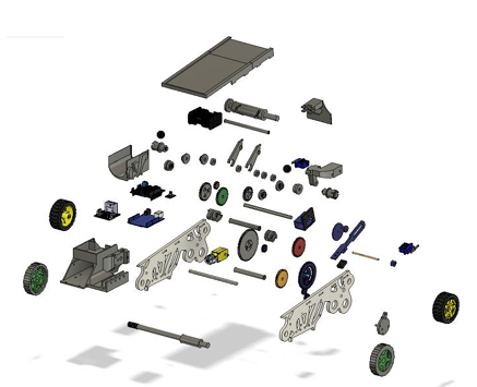
● Engineering Documentation: Produced exploded views, bills of materials, and engineering drawings for manufacturing and documentation
Design & Concept Development
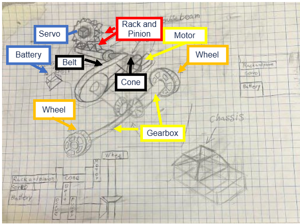
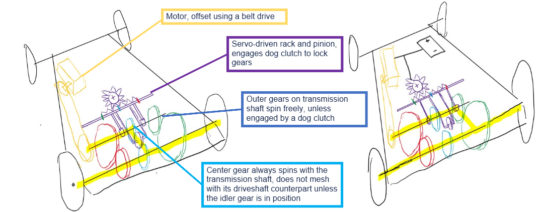
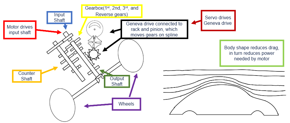
The project began by translating customer priorities into engineering design criteria, with an emphasis on speed, agility, shifting performance, and braking capability. Multiple drivetrain concepts, including sliding-mesh, constant-mesh, synchromesh, and CVT transmissions, were generated and evaluated using weighted Pugh matrices based on manufacturability, rigidity, cost, component count, shifting performance, feasibility, and ease of troubleshooting.
Three vehicle architectures were developed from the highest-performing concepts before proceeding to detailed design. A constant-mesh transmission was ultimately selected because it allowed gear changes by translating lightweight dog clutches rather than entire gears, reducing the moving mass required during shifts.
Mechanical Design
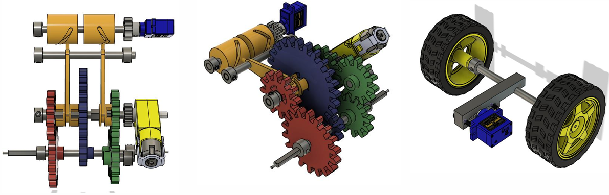
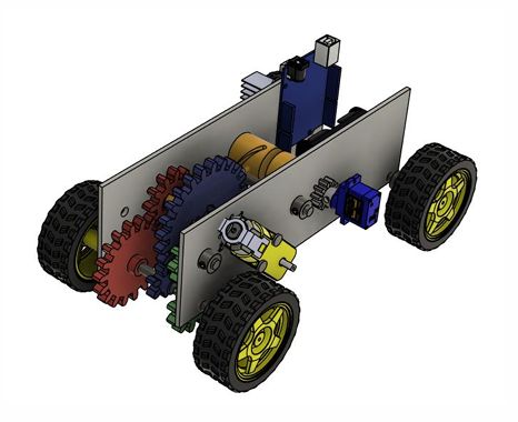
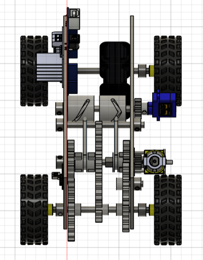
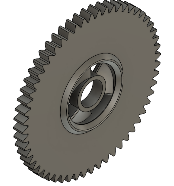
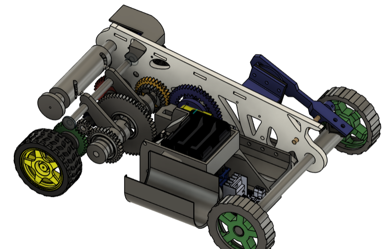
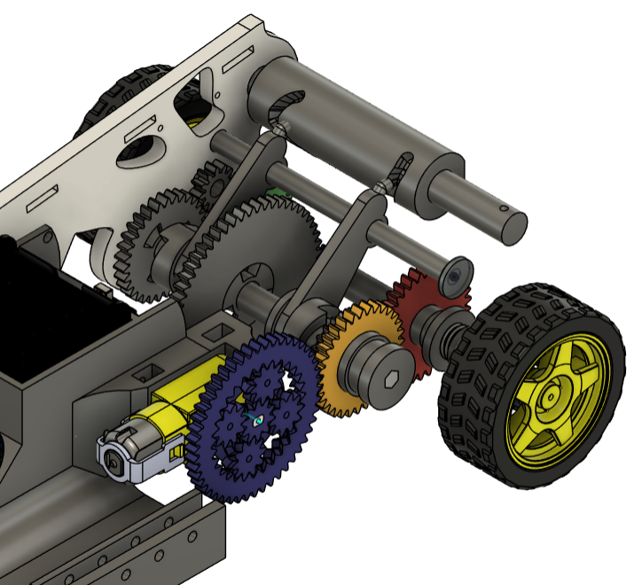
We developed a three-ratio constant-mesh transmission providing dedicated configurations for speed, strength, and reverse operation. Freely rotating gears were mounted on the transmission shafts and selectively locked using dog clutches and selector forks.
A servo-driven barrel-cam shifting mechanism converted servo rotation into controlled translation of the selector forks. Separate cam profiles controlled the two clutches, including a rapid transition between forward and reverse for agility testing. The final transmission incorporated 3:1 strength, 1:7.5 speed, and 1:1 reverse ratios.
A compact planetary reduction stage was later incorporated at the motor to increase available transmission input torque within the limited packaging space.
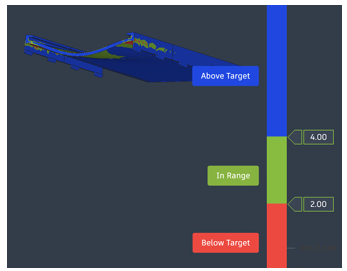
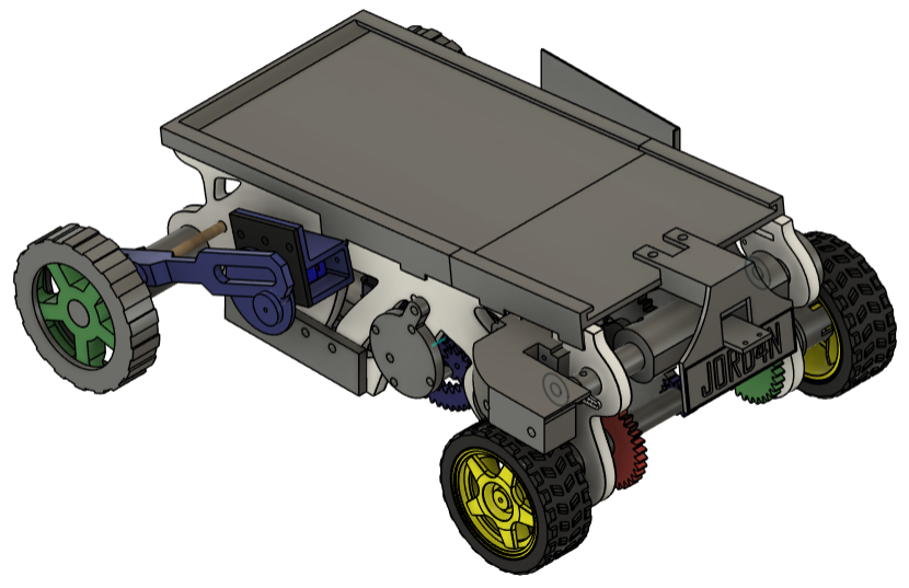
The vehicle also incorporated a servo-actuated short-shoe drum brake and Scotch-yoke linkage capable of locking the front axle independently of the driven wheels. The chassis was designed in Autodesk Fusion, with shape optimization used to reduce unnecessary material from the Delrin structural components.
Engineering Dynamics Analysis
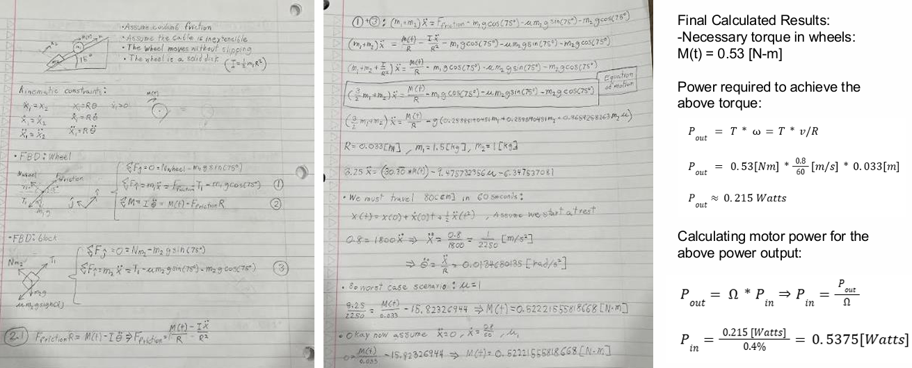
Vehicle dynamics models were developed to estimate the wheel torque, acceleration, motor power, and gear ratios required for the vehicle's performance targets.
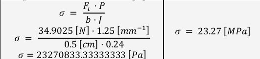
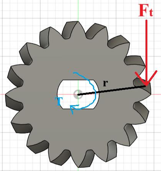
The PLA motor pinion gear was analyzed under the measured maximum motor torque of 0.1117 Nm. A Lewis bending analysis predicted a maximum tooth-root stress of approximately 23.3 MPa, corresponding to a factor of safety of 1.21 against the assumed PLA yield strength.
Finite element analysis was also performed on the vehicle's protective impact cover for a 3 kg durability load. An equivalent impact load of approximately 383 N was calculated and applied to the model. FEA identified insufficient safety margins around the PLA snap-fit connections, leading to the addition of a plywood reinforcement plate to the final design.
Prototyping and Iteration
The vehicle was manufactured using a combination of 3D-printed PLA components, laser-cut Delrin structural members, plywood, machined shafts, bearings, servos, and electronic components.
Physical testing revealed several issues that were not apparent during CAD development. In particular, the original barrel-cam geometry produced excessive resistance and did not account for the servo's actual angular travel. The shifting mechanism was subsequently redesigned by:
Reducing required cam travel from 180 degrees to 160 degrees
Replacing the original embossed cam path with a smoother swept profile
Reducing 3D-print layer height from 0.20 mm to 0.08 mm
Lengthening the dog clutches to improve engagement
Iteratively adjusting transmission geometry and component tolerances
Testing also revealed significant drivetrain friction distributed across multiple transmission components. The drivetrain was repeatedly disassembled and evaluated, with component reduction and lubrication used to decrease losses.
Controls & Testing
Finally, we programmed an IR remote-control system to control the drivetrain motor, transmission servo, and braking servo. Individual buttons commanded specific transmission states, while additional 15-degree servo adjustment commands were implemented to assist with transmission calibration and troubleshooting.
The completed prototype successfully demonstrated the mechanical architecture, braking system, electronic controls, and multiple drivetrain configurations. Persistent drivetrain friction ultimately prevented the high-speed gear from operating reliably during final testing, limiting performance in the speed, strength, and agility events, while the vehicle met or exceeded its requirements for quality, cost, and efficiency.
Engineering Takeaways
The project demonstrated the importance of designing mechanical systems around manufacturing tolerances, friction, assembly, and real actuator limitations rather than idealized CAD geometry alone. Iterative prototyping was essential for improving the barrel-cam and dog-clutch mechanism, while the difficulty of repeatedly disassembling the integrated drivetrain highlighted the value of design-for-assembly and subsystem-level testing in future prototypes.
Tools & Skills: Autodesk Fusion 360 • CAD & Mechanical Design • Transmission Design • Gear Design • Pugh Matrices • Machine Component Analysis • Finite Element Analysis • Design Optimization • 3D Printing • Laser Cutting • Arduino/Embedded Controls • Prototyping • Design for Assembly • Engineering Testing